

FLUXOGAZ : instructions d'utilisation / Instructions for use of the appliance
Assembly
The appliance is connected in series to the gas pipe alone(Acétylène, Propane, Hydrogen, etc; pay attention to the obligatory direction of the gas, shown by an arrow stamped on the tap body.
Loading
This is done throught the cap 8; during this phase valves 4 and 5 must be closed (that is with the black hand-wheel in horizontal position). Pressure is loaded by closing the gas valve and opening the blowpipe. Deoxidizer may be loaded up to the rim of the cap seal and adjust.
Adjusting
The tap body has been conceived in such a way as to achieve easily the best distribution of flow in the flame, allowing total exclusion of flow when necessary. When tap 1 is opened gradually, the concentration of déoxidizer in the gas comming out is decreased until the required adjustement is achieved.
1 open 4 and 5 closed gas without deoxidizer .
Do Not Use Gas Pressures higher than 0.5 - 0.6 atm.
Do Not Overturn The Appliance During Opération.
All déoxidizers are inflammable.
Switching off
At the end of the welding, close the pressure reducers and the valve 5 to prevent the rise of borax, then discharge the pressure by opening the gas blowpipe and closing valve 4.
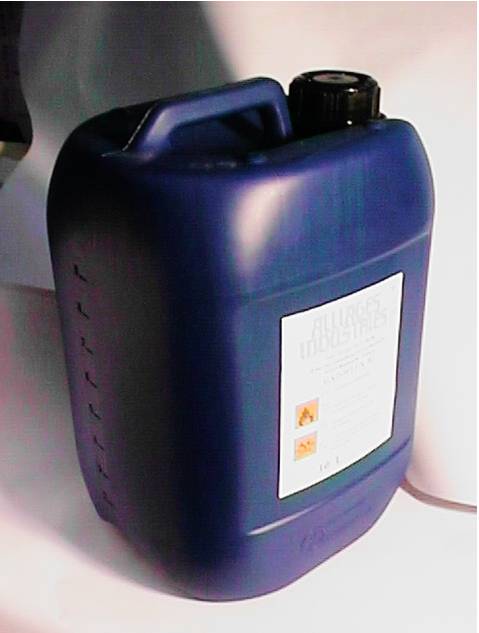
FLOXUGAZ Deoxidizer
| Valves | Results | |
|---|---|---|
| 1 Open / 4 and 5 Closed | => | Gas without deoxidizer |
| 1 Closed / 4 and 5 Open | => | Gas with deoxidizer |
Concentration is regulated with 1
STOP => Close the pressure reducers5 Closed => let's go the Gas => 4 Closed
DO NOT USE GAS PRESSURES HIGHER THAN 0.5 - 0.6 atm.
DO NOT OVERTURN DURING OPERATION
ALL DEOXIDIZERS ARE INFLAMMABLE
Schema
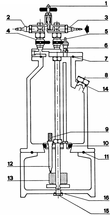
- Adjusting Tap
- Output coupling for gas + déoxidizer.
- Gas input coupling
- Ball valve
- Ball valve
- Safety valve set 2 Bar
- O - ring
- Loading Cap
- Filter
- O - Ring
- O - Ring
- Déoxidizer transfer injector
- Déoxidizer level float
- O - Ring
- Discharge cap
- O - Ring